![]() The Points of Interest view was introduced in Version 6 of AiDamage. The purpose of this paper is primarily to explain how the point of interest data is calculated and displayed. It also provides hints as to how data generated from AiDamage can be compared with accelerometer based data obtained directly from a vehicle.
The Points of Interest view was introduced in Version 6 of AiDamage. The purpose of this paper is primarily to explain how the point of interest data is calculated and displayed. It also provides hints as to how data generated from AiDamage can be compared with accelerometer based data obtained directly from a vehicle.
Selecting the Points of Interest option causes AiDamage to display a page showing the motion of any specified point of interest within the vehicle. Although the motion of the centre of mass of the vehicle and the point of application of the impulse are important and already used in the calculations, the motion of any other point within the vehicle may be of interest to an investigator too. For example, the acceleration sustained by a sensor located in the air-bag module may be noteworthy, or a sensor located remotely such as a lateral velocity sensor in the ‘B’ pillar.
Using this view option allows such a point of interest to be defined and output similar to that obtained by a Crash Data Retrieval (CDR) tool to be generated. In turn this permits a direct comparison to be made between the output of AiDamage and the CDR.
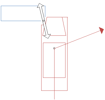
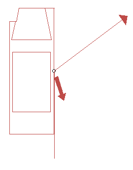
It is important to appreciate that every point within a vehicle sustains a different change in velocity (Delta-V) and acceleration as a result of the collision. To explain this, consider a simple offset head-on impact between a car (in red) and a barrier (in blue) as shown in Figure 1
It is clear that if this were a real collision, the red vehicle would pivot anticlockwise about the impact point. Various points within the vehicle move post-impact as shown in Figure 2.

In reality (and in the AiDamage model), it can be seen that the centre of mass does not continue in a straight line either but changes direction to the right. This is shown by the direction vector in Figure 1. Since the direction of the impulse (the PDOF) is defined by the change in motion of the centre of mass, this implies that there must be a small lateral component to the impulse relative to the vehicle. This is shown by the double-headed impulse vector arrow in Figure 1.
Prior to impact all the points of the vehicle have the same velocity (assuming as AiDamage does, that there is no, or insignificant pre-impact rotation) Since each point within the vehicle has a different post impact motion, it is apparent therefore that the Delta-V (Δv) of each point must be different too since the vector quantity Δv is defined as a change in velocity

These differences are due to rotation of the vehicle as a result of the impact. The only situation where all the points within a vehicle have the same Delta-V is when there is no rotation and this only occurs when the impulse passes through the centre of mass.

To show how Delta-V is distributed throughout the vehicle in this particular example, Figure 3 shows the direction of Delta-V at the same selected points as in Figure 2. Note that the Delta-V vector arrow in this diagram are not scaled and simply show the direction of the Delta-V of each point.
In general, the Delta-V of any point within each of the vehicles can be calculated as the Delta-V of the centre of mass PLUS the Delta-V calculated from the distance of the point from the centre of mass due to the change in rotation as a result of the collision. As a equation this can be written

where the subscripts p and c indicate the change in velocity of the point of interest and centre of mass respectively, ω is the angular velocity and r is the position of the point of interest relative to the centre of mass. Note that this is a vector equation so the X symbol here indicates the vector cross product, not ordinary multiplication.
AiDamage has always used this equation to determine the motion of the point of application of the impulse and how it is derived is described more fully in the User Manual. In effect, all that has been done with the new Points of Interest view is to extend that idea to deal with any point within either of the vehicles.
Further to this, if the duration of the impact pulse is known or can be assumed then the Delta-V can be restated as an acceleration. Typically an impact occurs with an impulse of between 150 and 250 milliseconds and AiDamage assumes by default a value of 250 msec. If access to the output from a CDR is available, then the actual duration of the impact can be determined from that document and specified in AiDamage. There are tools in the Ribbon bar to control the duration of the impulse.
In any event, unless a real sensor in a vehicle is located exactly at the centre of mass, then the output from the main screens of AiDamage are unlikely to match the Delta-V recorded by that sensor. The sensor can only ever record what it is experiencing and as can be seen this is highly likely to be different in both magnitude and direction to that of the centre of mass.
Several models assuming various shapes for the impulse acceleration are available in AiDamage. Uniform, triangular, sinusoidal and normal distribution (Gaussian or bell-shaped) curves are available. The basic shapes of these curves for the same total Delta-V and assuming an impulse duration of 250 msec are shown in Figure 4
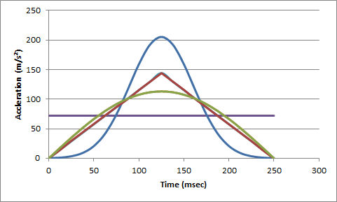
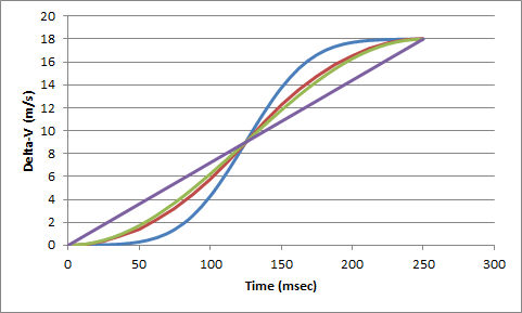
Note that the total area under each of the curves in Figure 4 (between 0 and 250 sec) is the same for each shape curve and represents the total Delta-V experienced by the point of interest. The rate at which the total Delta-V accumulates can also be calculated from each of the curves which then produces cumulative Delta-V curves as shown in Figure 5
CDR tools often display a table of the data so AiDamage replicates that feature too. Consider a sensor located for example at the right-hand side ‘B’ pillar. A diagram showing the motion of that point of interest is shown in Figure 6.
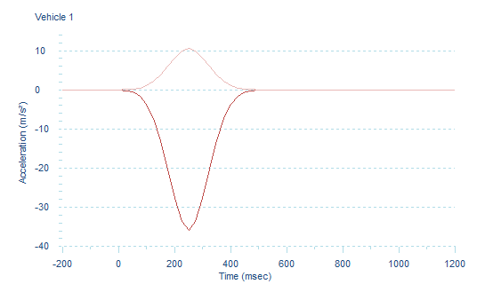
A sample of the graphical output generated by AiDamage is shown in Figures 7 and 8. This sample shows data and graphs for the lateral and longitudinal acceleration experienced by the centre of mass assuming a normal distribution shaped impulse. Acceleration and Delta-V are both vector quantities so the lighter coloured trace shows the lateral component and the darker trace the longitudinal component. Similar graphs are provided for the motion of vehicle 2 as well.
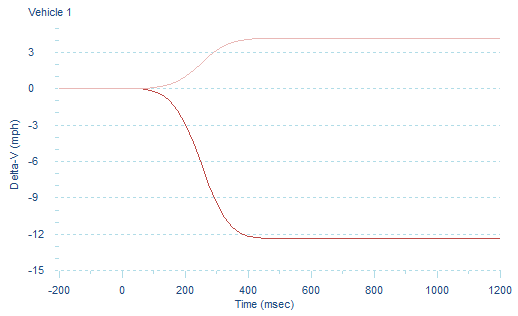
The graph in Figure 8 shows the cumulative component Delta-V output for the same sensor located at the right-hand side B-pillar.
In all collisions a series of options are available in the Ribbon bar to switch the view to show any of the impulse models and cumulative Delta-V. The top diagram shows the impact configuration, the paths of the point of interest and an arrow showing the direction of the change in velocity of the point. The data shows whatever data is generated according to the impulse shape model selected and the graphs show both the lateral and longitudinal acceleration or cumulative Delta-V.
Several options are available using the commands in the ribbon bar or in the context menu which may be of assistance and the diagram itself can be scaled to suit. Options are available to turn on or off the display of the impulse vector arrow, the overlay of the damage profile, the motion of the point of interest and the Delta-V arrows.
The motion of the centre of mass, the centre of the vehicle and the point of application of the impulse are available as preset points using the drop down Type button for each vehicle. There is an option too to select a user defined point within the vehicle. Either type in the location of each of the points relative to the centre of mass of the vehicle, or use the spin-buttons to shift the point of interest. Once the point has been defined, selecting the Save button for each of the vehicles saves the location of the user defined point of interest so that it too can be selected using the drop down Type button.
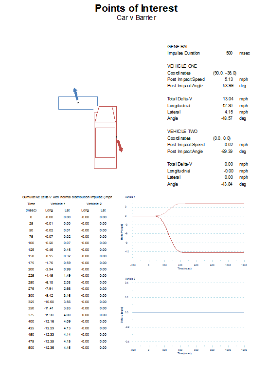
For completeness, an image showing the entire Point of Interest page as it would appear when printed is shown below.